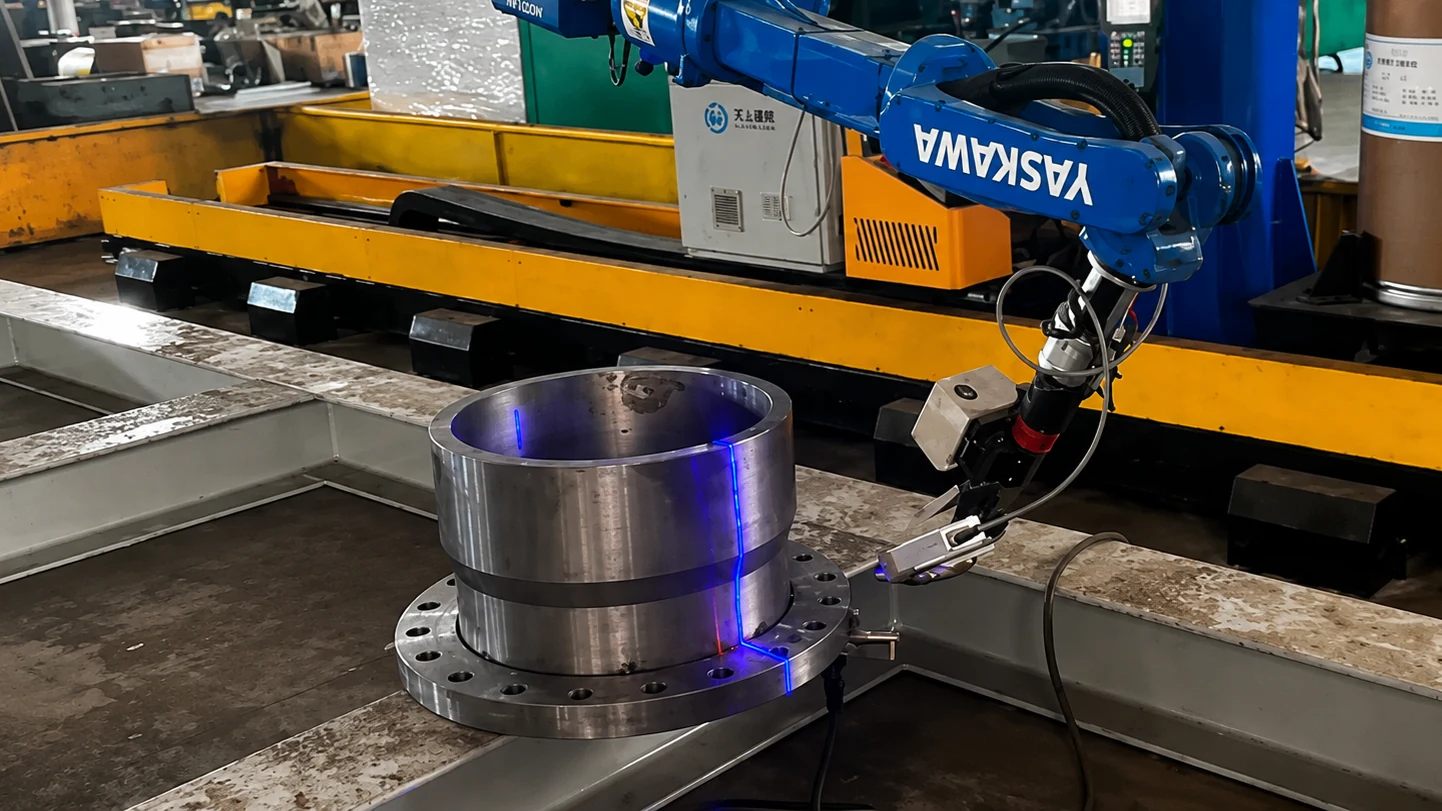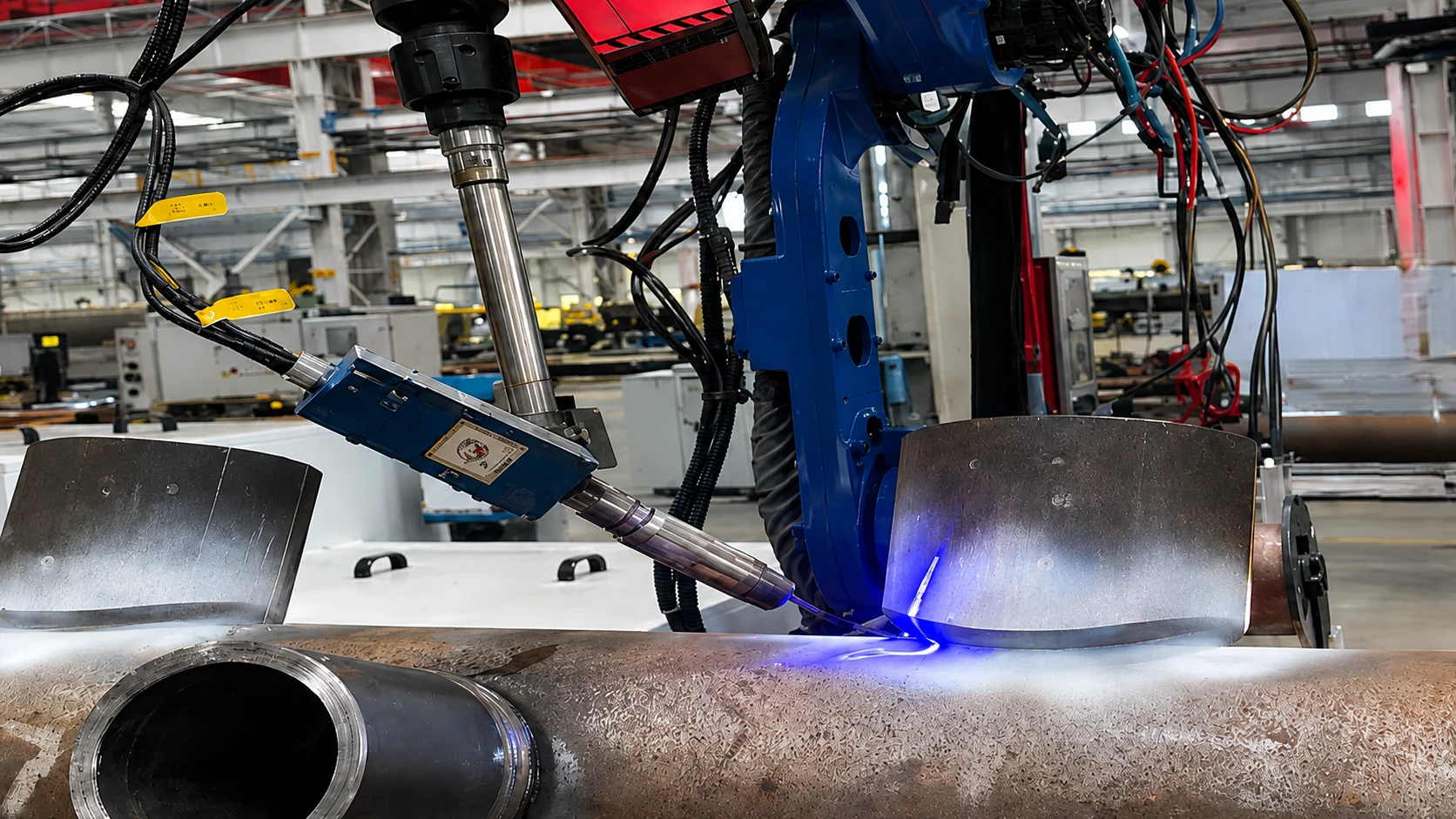
Conventional teaching
Point-by-point teaching and program creation
Paths are memorized with a teach pendant and run on fixed positions. Mix changes and geometry variation send the job back to the teaching specialist.
For one-offs, high-mix production, and workpieces that differ in specification or geometry, recognition, planning, and execution are configured as one robotic welding system. The premise shifts from re-teaching paths on every mix change to re-capturing the actual workpiece.
Robotic welding automation Featured application: H-beam Customer-facing deployment on record
In conventional robotic welding, operators use a teach pendant to program start points, end points, and turnaround points one by one. Torch orientation, collision avoidance, and positioner coordination are built into the program. When the workpiece changes, that work has to be done again.
The robot follows memorized paths. High-mix, low-volume work, one-offs, frequent changeovers, and shifts in actual workpiece position or shape make fixed-path assumptions fragile. Teaching itself often becomes the setup bottleneck.
Conventional teaching
Paths are memorized with a teach pendant and run on fixed positions. Mix changes and geometry variation send the job back to the teaching specialist.
Vision-based automation
3D sensing captures the actual workpiece, weld candidates are recognized, and paths are generated from the targets, order, and parameters the operator selects. Before welding, a torch-side proximity sensor locates start and end points; where needed, arc tracking corrects deviation during the weld.
The difference is how preparation is done and how variation is handled.
The operating concept is to re-capture the actual workpiece, present recognized weld candidates for operator confirmation, and generate robot motion from the confirmed targets, parameters, and sequence. Sensing and correction are then applied according to the joint and application.
AGR does not deliver cameras or software alone. Vision, planning, robot, welding, and control are integrated as one system. Units are combined to match the project.
Planning
Weld tasks and path plans are built from recognition results and the weld targets, parameters, and order set by the operator.
Wide-area recognition
Overall workpiece position, orientation, and geometry are captured at a wide scale.
Local locating
A torch-side proximity sensor confirms start and end points and corrects position relative to the generated trajectory.
Execution
The robot that executes the planned path, plus any required peripheral axes.
Welding
Power source, torch, wire feed, and related welding execution hardware.
Integration
Recognition, planning, and execution are connected under one control architecture.
Application examples include building steel structures, bridges and steel frames, ship sub-assemblies, deep-groove bulkheads, environmental equipment, flanges, circular workpieces, long members, pressure vessels, and railway parts. Fit depends on confirming workpiece conditions.
A. Structural members
Rib locations, member length, and joint positions change from workpiece to workpiece. Conventional teaching stacks point re-teaching and program management.
The actual workpiece is scanned so members and ribs are recognized and candidate seams are extracted. On H-beam, the operator selects targets before the path is generated. For long members and steel frames as well, the starting point is actual geometry—not a fixed path.
B. Complex geometry and spatial welding
Spatial joints, arcs, and nozzle regions often take long point-teaching cycles for path and torch orientation.
Model-plus-vision or adaptive control is used to build paths while accounting for actual-position offset. Pressure vessels are not treated as pure teachless. Ship sub-assembly examples are for the sub-assembly stage—not full hull shipbuilding specialization.
C. High mix and frequent changeover
Mix is high and the same fixtures and programs are hard to keep for long. Conventionally, each changeover returns to teaching.
Setup centers on actual-workpiece recognition and task configuration. Railway parts are application examples from collaborative projects. Environmental equipment can also be addressed.
There is more than one path to this automation. Teachless is one technology class. Classes are selected by project.
A
Starts from sensing the actual workpiece and reduces dependence on hand teaching per workpiece. CAD is not always required. This class has advanced first on high-mix work such as H-beam.
B
Uses an existing model or workpiece definition and corrects actual position and deviation with vision. Suited to complex geometry where model information is useful.
C
During 3D measurement and welding execution, position, torch orientation, and welding parameters are corrected to match actual conditions. Pressure-vessel nozzle welding is adaptive control / model-plus-vision—not pure teachless.
See recognition and path-generation detail in Technology & Validation →
AGR is not a software-only vendor. From application definition through startup, the work is designed as a welding automation system.
Conventional teaching cells are not obsolete. For a single product, higher batch sizes, stable geometry, and programs that rarely change, a Robotic Welding Cell is often simpler and more practical.
Good fit
High-mix low-volume, one-offs, frequent workpiece changeover, actual-workpiece variation, and non-standard structural members. Consider this when conventional point-teaching burden is high.
When a cell is more practical
If a defined part family runs the same program on fixtures and positioners, evaluate a conventional cell first. Teachless is not superior for every welding job.
H-beam is a featured application in this category. The actual workpiece is 3D-scanned; the H-beam and ribs are recognized and candidate seams are extracted. The operator selects targets, sets welding parameters and any required weld order, then the system generates the robot program and motion path. Interference is checked in PC simulation. Before welding, a torch-side proximity sensor locates start and end points. The operator then confirms and starts the welding cycle.
Deployment on record. The robotic H-beam welding system has customer-facing deployment on record. After scanning, the system does not automatically decide every seam and weld through without operator confirmation.
On H-beam, after scanning the operator selects and confirms weld targets, sets parameters and order, then the weld program and path are generated. After generation, interference is checked in PC simulation before execution.
Place and prepare the H-beam to match fixture and support conditions.
Read the placed workpiece with a 3D scan, or use an existing 3D model.
Process point-cloud data and recognize / model the H-beam body and rib positions, count, and condition.
Candidate weld seams are extracted from recognition results and shown on screen.
Select and confirm the required seams. Unnecessary seams can be excluded by the operator.
Set welding parameters and any required weld order.
From the settings, software calculates intermediate trajectories between start and end points and auto-generates the robot program and motion path.
Generated motion is simulated on a PC to check interference, and the operator confirms execution. Before welding, a torch-side proximity sensor locates seam start and end points; the confirmed cycle can then start. Where needed, arc tracking corrects deviation during the weld. Short seams and similar cases may run without arc tracking.
Review machine configuration and motion. Video loads and plays after click (no autoplay).
Video loads and plays after you select it; autoplay is disabled.
For the same workpiece after weld targets and parameters have been set once, existing settings can be reused. If workpiece placement is within an acceptable range, production can start without repeating the full first-time setup. Acceptable offset and conditions are confirmed per workpiece and equipment configuration.
Actual-workpiece recognition, candidate-seam extraction, auto-generation of robot program and motion path, start/end locating, and arc tracking when needed
Selecting and confirming required seams, setting welding parameters and any required weld order, checking interference in simulation, and confirming content before execution
Robotic H-beam welding supports both using an existing 3D model and generating a model from a 3D scan of the actual workpiece. Even when a 3D model is available, the operator still sets and confirms weld targets and parameters. In other technology classes, model information can be useful.
Application example from a live project
An application for recognizing and sequentially welding small parts with different geometries in a high-mix workflow.
View details
Application example from a live project
An adaptive-control application that measures the three-dimensional nozzle-joint geometry and plans weld layers and paths around the actual groove geometry.
View details
Teachless describes methods that reduce dependence on conventional point-by-point teaching by recognizing the actual workpiece and generating paths. It is not a standalone product category. In AGR High-Mix Robotic Welding Automation, teachless / model-free approaches are used alongside model-plus-vision and adaptive control, depending on the project.
Conventionally, an operator uses a teach pendant to program start points, end points, turnaround points, torch orientation, collision avoidance, and positioner coordination point by point. When the workpiece changes, programs often have to be rebuilt. High-mix approaches combine 3D sensing, workpiece recognition, weld-candidate extraction, path planning, and position correction. Applicability still depends on workpiece conditions.
In high-mix, low-volume or one-off production, teaching effort accumulates every time the workpiece changes. Starting from re-sensing the actual workpiece and building the path helps reduce dependence on robot point teaching and can ease changeover setup. For high-volume repetition of the same workpiece, a conventional teaching cell may still be the more practical choice.
Yes. Robotic H-beam welding is a mature featured application. The same approach can apply to building steel structures, bridges and steel frames, ship sub-assemblies, deep-groove bulkheads, environmental equipment, flanges, circular workpieces, long members, and similar work. Railway parts and pressure vessels have application examples from collaborative projects. Fit still depends on confirming workpiece conditions.
No. Teachless / model-free approaches start from sensing the actual workpiece and reduce dependence on hand teaching per workpiece. When model information is useful—for example on complex geometry—a model-plus-vision approach is used. CAD is not always required. For H-beam, both existing 3D models and 3D scans of the actual workpiece are supported.
No. On H-beam, after scan and recognition the system displays candidate weld seams. The operator selects and confirms targets, then sets welding parameters and any required weld order. From that input the system generates the robot program and motion path and checks interference in simulation. The operator then confirms the result and starts the welding cycle. Other technology classes use different confirmation steps by project.
A robotic welding cell is equipment built as one package—fixtures, positioners, and sensing—around a defined part family. High-Mix Robotic Welding Automation focuses on re-capturing weld targets through recognition and path generation when workpiece shape or mix changes. Robotic H-beam welding is a featured application of that approach.
Yes. When the work is a stable part family with consistent geometry and programs that rarely change, a robotic welding cell is often simpler and more practical. Teachless is not superior for every welding job.
AGR provides remote and on-site technical support for delivered systems, including installation and commissioning, operator training, system setup, troubleshooting, maintenance support, and production ramp-up. Service scope is coordinated according to the system configuration, delivery region, project requirements, and agreed service arrangement.
Engineering support and technical coordination for delivered AGR systems.
Toronto, Ontario, Canada — regional communication and service coordination for North America.
Incuba Navitas, Inge Lehmanns Gade 10, 6th Floor, DK-8000, Aarhus C, Denmark — regional communication and service coordination for Europe.
+45 5376 5172
[email protected]
Regional parts availability: Common consumables and selected service parts can be stocked regionally based on installed systems and service requirements to reduce parts lead time and support faster maintenance response.
Photos or drawings of workpieces that change in shape—H-beam or otherwise—help the technical review move forward.
Discuss Your Application Request a Technical Assessment