
Follow specification changes and complex weld geometry.
In pressure vessels and process equipment, specifications change by batch, and nozzle attachment intersections become space curves. Stabilizing multi-layer multi-pass welding with fixed programs alone is difficult in this field.
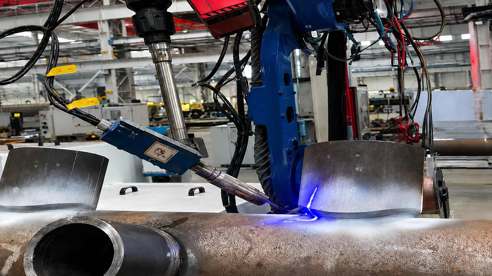
Industry image (not a photo from a real project)
Complex geometry and batch-by-batch specification change.
- Weld zones that become space curves, such as nozzle attachments
- Specifications that change by batch
- Multi-layer multi-pass welding assuming thick wall and full penetration
- Position and process correction between passes
The nozzle-joint geometry is measured in 3D, weld layers and paths are planned, and subsequent passes can be corrected using re-measurement of position, torch orientation, and welding conditions.
Application example from a real project
Three-dimensional nozzle-attachment geometry is measured, and layering and weld paths are planned to match the groove shape. After each pass, the workpiece is re-measured and the next pass’s position, torch attitude, and welding parameters are corrected. One example of welding automation that follows specification change.
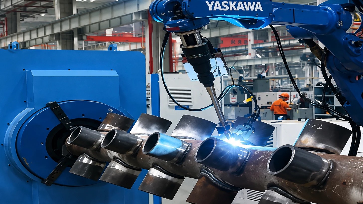
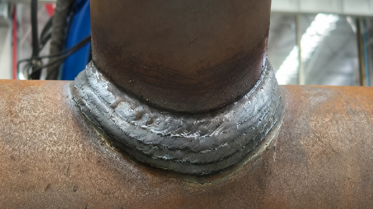
An adaptive-control path within High-Mix Robotic Welding Automation.
Challenges in this field map to model-plus-vision / adaptive-control applications within High-Mix Robotic Welding Automation. Refer to Robotic Welding Cells only when the search is specifically for a cell layout.
Application examples in this field
Discuss pressure vessels & process equipment
Joint geometry, thickness, and multi-layer multi-pass welding conditions help the first assessment move faster.
Request a Technical Assessment