
Delivered / in-production evidence
Delivery and operating materials are shared according to project conditions.
A robotic welding cell automates welding for a defined part family. AGR evaluates the workpiece through safety design as one cell architecture, then designs and commissions a system built for production use.
This is a different role from High-Mix Robotic Welding Automation, which assumes changing workpieces and recognition-driven path generation. A cell is built to weld defined part families stably under fixture-based conditions.
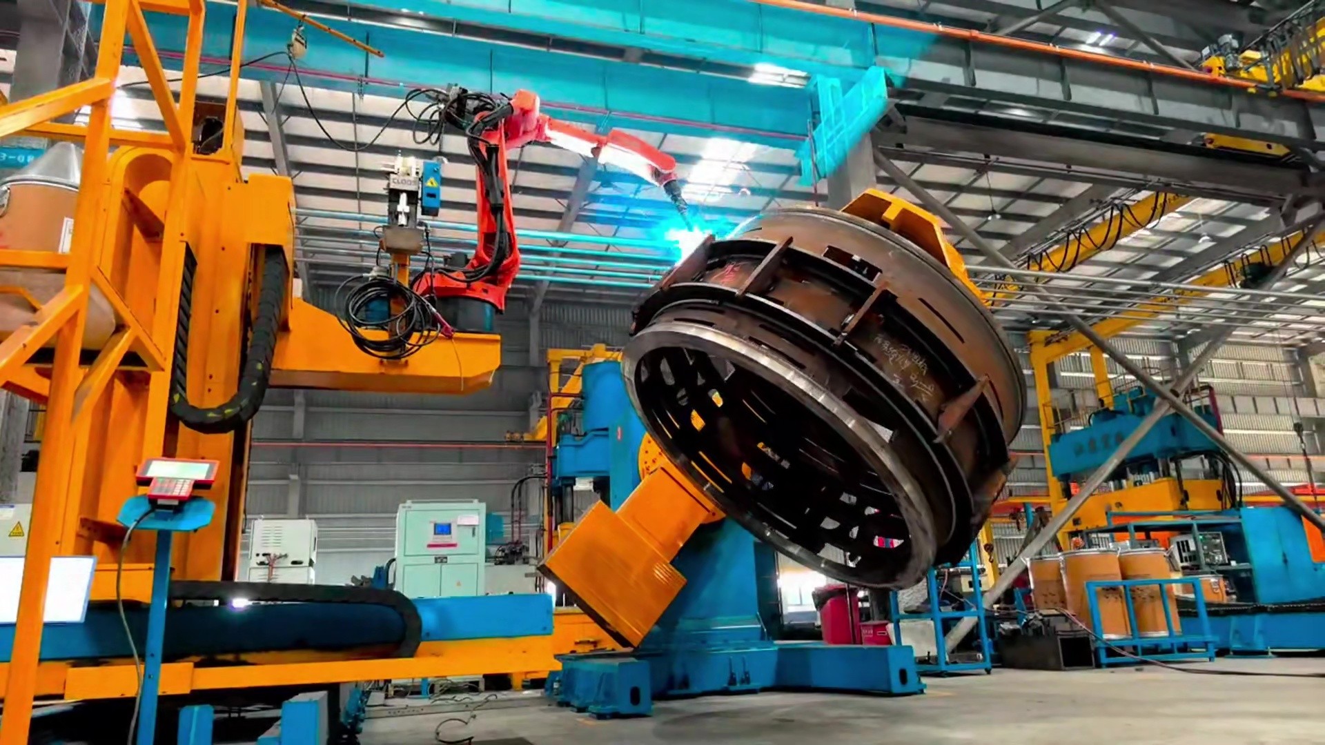
Robotic welding cells suit dedicated processes, stable repeat production, identical or similar part families, and localized automation. Typical triggers include weld quality variation, dependence on skilled welders, rising volume, and changeover burden. If the main issue is re-teaching every time workpiece geometry changes substantially, start with High-Mix Robotic Welding Automation. Cells and high-mix automation are not the same concept.
Video of cell configuration—including robot, welding power source, fixtures, positioners, and safety—and actual welding motion. Playback starts after click; no autoplay.
Video loads and plays after you select it; autoplay is disabled.
Confirm material, thickness, joints, torch access, and quality requirements.
Select for workpiece size, reachability, and welding conditions.
Custom design from restraint, attitude, and setup conditions.
Real-workpiece compensation, safety systems, trial validation, install and ramp-up.
Fixtures, positioners, travel axes, sensing, and safety are designed around the workpiece and plant environment. AGR does not stop at the robot arm: welding power sources, external axes, controls, and—when required—vision and seam tracking are integrated into the cell. Concept, design, build, and commissioning stay under one engineering responsibility.
Elements that can be integrated into the cell
Robot, welding power source, fixtures, positioners, and travel axes are coordinated as one cell, with travel axes and positioners controlled as external robot axes. Concept through fabrication, installation, and commissioning stays in-house.
Manual, pneumatic, or hydraulic fixtures designed around workpiece geometry, dimensions, weld attitude, and setup conditions.
Positioners, travel axes, and lift/rotate mechanisms sized for workpiece weight, center of gravity, envelope, and required weld attitudes.
Touch sensing, arc sensing, seam tracking, fume extraction, guarding, door interlocks, and related safety controls as needed.
On thick-plate structures and construction-machinery parts, cutting, forming, and tack-up tolerances stack up. Actual joint location and root gap vary. Fixtures alone cannot fully remove that variation on large or thick-plate workpieces. AGR therefore combines fixture-based basic positioning with sensor-based real-workpiece compensation.
Hold reference location and weld attitude with fixtures and positioners. Accuracy is not assumed to come from fixtures alone; compensation follows.
Touch sensing detects weld location and corrects offset. Root gap can be measured when the process requires it.
During welding, arc sensing or laser seam tracking corrects joint deviation as the weld progresses.
Measured root gap can inform welding-parameter selection for the gap width. Sensors and algorithms are selected for joint geometry, thickness, and material conditions, then integrated into the cell.
Trial builds and weld tests confirm appearance, internal quality, and distortion considerations. Conditions are refined before installation and commissioning. Where inspection requirements apply, they are reviewed during process design.
| Typical focus | Thick-plate structural parts and part families suited to repeat production |
|---|---|
| System elements | Robot, welding power source, fixtures, positioners, external axes, controls, safety; vision and seam tracking when required |
| Review items | Thickness, joints, torch access, quality standards, takt, maintenance |
| Boundary | Not a universal cell—each part family needs application evaluation |
Delivery and operating materials are shared according to project conditions.
Trial builds and weld tests confirm quality considerations.
Proposal-stage reference drawings are distinct from delivery evidence.
AGR Group factory production line for construction-machinery boom and arm welding.
Customer deployment of robotic welding for agricultural machinery components.
Customer deployments of robotic welding systems for combustion and flare equipment fabrication.
A robotic welding cell is production equipment that automates welding for a defined part family. Robot, welding power source, fixtures, positioners, sensing, and safety are engineered together as one cell and configured around the workpiece conditions.
Cells work well when you focus on a defined part family and need more stable setup and weld quality. Typical triggers include weld quality variation, dependence on skilled welders, rising volume, and changeover burden.
No. AGR designs the cell as an integrated system: workpiece and weld-process evaluation, robot and power-source selection, fixtures and positioners, external axes, controls, sensing, safety, trial validation, and commissioning. Vision and seam tracking are included when the application requires them.
Fixtures and positioners establish basic location and attitude. Touch sensing then finds weld locations and corrects offset; root gap can be measured when needed. During welding, arc sensing or laser seam tracking can correct joint deviation as the weld progresses.
Yes. Guarding, door interlocks, and safety controls are engineered into the cell for the plant environment and welding conditions.
From concept stage, AGR confirms workpiece conditions, validates quality through trials and weld tests, then installs and commissions the system. Applicability is judged from part geometry, thickness, volume, and inspection requirements.
AGR provides remote and on-site technical support for delivered systems, including installation and commissioning, operator training, system setup, troubleshooting, maintenance support, and production ramp-up. Service scope is coordinated according to the system configuration, delivery region, project requirements, and agreed service arrangement.
Engineering support and technical coordination for delivered AGR systems.
Toronto, Ontario, Canada — regional communication and service coordination for North America.
Incuba Navitas, Inge Lehmanns Gade 10, 6th Floor, DK-8000, Aarhus C, Denmark — regional communication and service coordination for Europe.
+45 5376 5172
[email protected]
Regional parts availability: Common consumables and selected service parts can be stocked regionally based on installed systems and service requirements to reduce parts lead time and support faster maintenance response.
Share target parts, thickness, volume, and inspection requirements.
Discuss a welding cell