
A. Robotic bevel cutting
Robotic bevel cutting
Recognizes contours and bevel geometry on thick-plate structural parts, then generates gas-cutting paths for bevel preparation. Applied in factory production settings.
Bevel cutting and chamfering are different processes. AGR automates weld preparation — not welding itself. Current scope is automated bevel cutting by gas cutting. Chamfering is engineered separately as a teachless chamfering robot.

Robotic bevel cutting (gas) automates gas-based bevel preparation as its own process. It does not require a welding cell installation.
Welding vision targets joints and weld candidates. Bevel vision targets edges, contours, bevel geometry, and as-built dimensions. Because the sensing targets differ, the vision architecture is designed separately from welding. This is not a shared system with only the end-of-arm tool swapped.
Bevel cutting shapes the weld joint. Chamfering finishes edges. Compatible chamfering robot configurations can also deburr, but the three are not interchangeable.
A. Robotic bevel cutting
Recognizes contours and bevel geometry on thick-plate structural parts, then generates gas-cutting paths for bevel preparation. Applied in factory production settings.
B. Independent pre-weld process
A teachless chamfering robot that finishes edges using 3D vision recognition and path generation matched to workpiece geometry. It is not an accessory to bevel cutting.
Bevel cutting prepares parts for downstream fit-up and welding. The system recognizes as-built workpiece geometry, prepares the bevel, and reduces repeated hand programming per workpiece. Quality and productivity outcomes depend on workpiece conditions.
A teachless bevel cutting robot is a cutting system that couples 3D workpiece recognition with robot motion. The robot does not only cut — recognition, planning, cutting, and control are engineered as one system.
Captures overall workpiece position, orientation, and contour.
Confirms local cut location and bevel geometry at the cutting zone.
Bevel preparation by gas cutting.
Add external axes when reach or torch orientation requires it.
Plans cutting tasks and paths from recognition results.
Links recognition, planning, and cut execution under one control architecture.
Application directions include construction machinery, mining equipment, bridge steelwork, shipbuilding, and wind energy. High-mix, low-volume one-off production is also in scope.
Layout is selected per application. Features are bound to configuration. Features of one form are not treated as common specification across every bevel system.
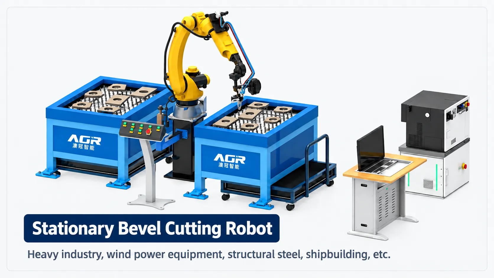
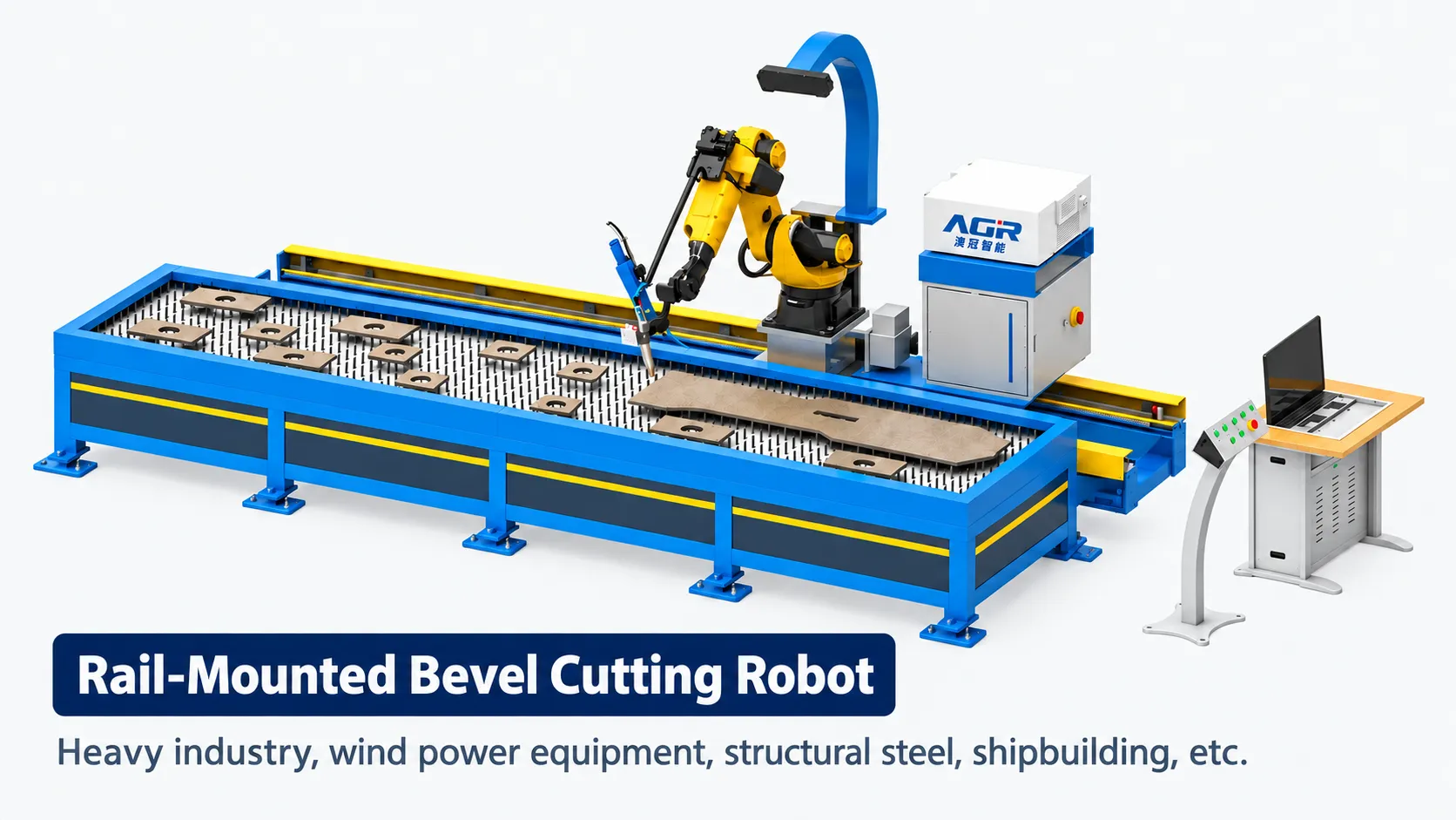
Fixed robotic bevel cutting
Suited to compact layouts and single- or dual-station workstations. Fixed configurations support mirroring visualization, batch processing, one-touch start, and continuous multi-workpiece processing.
Floor-traveling robotic bevel cutting
Moves across a wider area with 7-axis coordinated motion. Uses task planning and visualization, and can process multiple workpieces in batch. Suited to large members and sites where placement changes.
Bevel geometry and workpiece form vary by application.
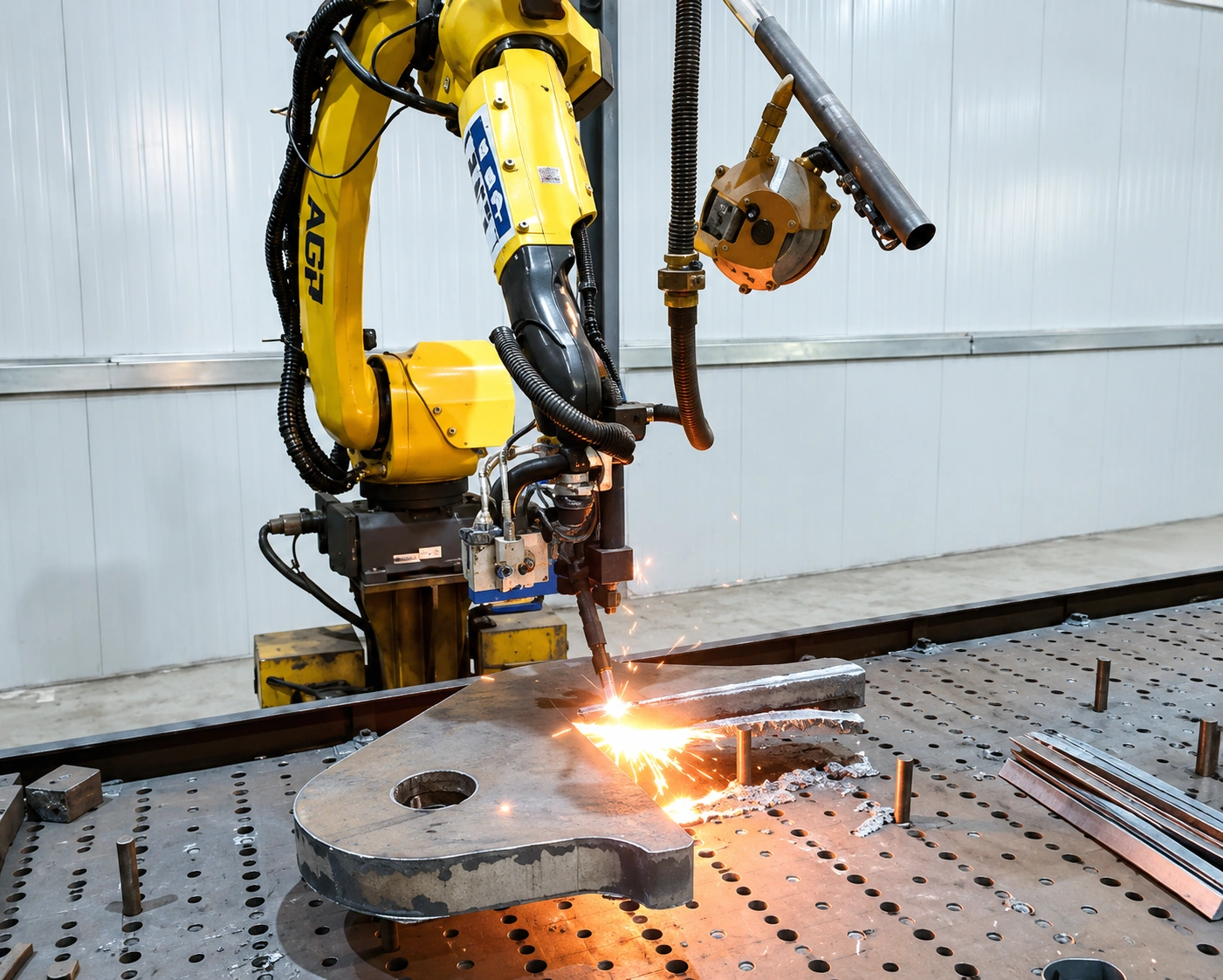
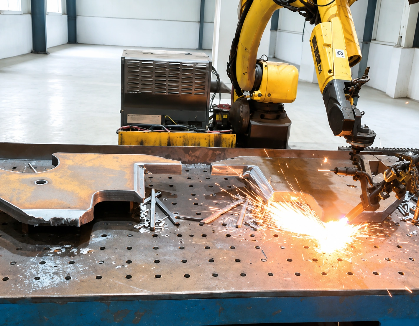
Representative forms are shown first; others are listed below. Final configuration is set from workpiece conditions.
Stationary layout with a defined work envelope. Single- or dual-station layouts that support continuous processing.
7-axis coordinated motion across a wide envelope. For large members and sites where placement changes.
Allows the next workpiece to be staged while cutting runs — suited to frequent changeovers.
Considered when long members or continuous infeed are required.
Additional configuration examples. Selected according to workpiece and production conditions.
Work proceeds through four stages: task definition, scan and localization, recognition and planning, and cut execution. The six steps below map that logic to shop-floor order.
01
Define what to cut and which bevel. Workpiece placement from the six-step flow belongs here.
02
Recognize the full workpiece and establish position and orientation.
03
Acquire contour and bevel geometry, then generate cut locations and paths.
04
Confirm the plan, start the cycle, and execute gas bevel cutting.
Position the target workpiece according to the task definition.
As scan and localization, recognize position, orientation, and shape. Uses a vision architecture distinct from welding rib recognition.
Capture edges, contours, bevel shape, and as-built dimensions.
As recognition and planning, set cut locations from acquired data.
Generate a path matched to bevel geometry and torch reach.
Cut execution. Confirm the plan, start the cycle, and run gas bevel cutting automatically.
Review machine configuration and motion. Video loads and plays after click (no autoplay).
Video loads and plays after you select it; autoplay is disabled.
A teachless chamfering robot automates chamfering with 3D vision. It is an independent pre-weld process — not an accessory to bevel cutting. It finishes edges such as hole perimeters, outer contours, and corners rather than cutting weld-joint geometry.
On compatible configurations, free-edge chamfering can include automated deburring as a secondary step. Deburring is available as an accompanying process on compatible chamfering robot configurations. The primary purpose is chamfering.
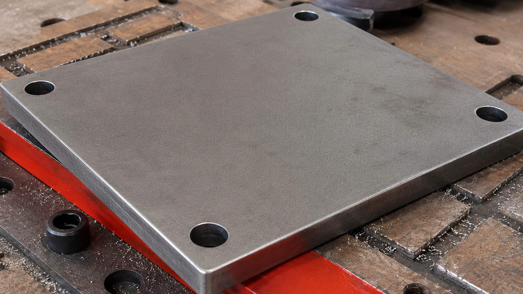
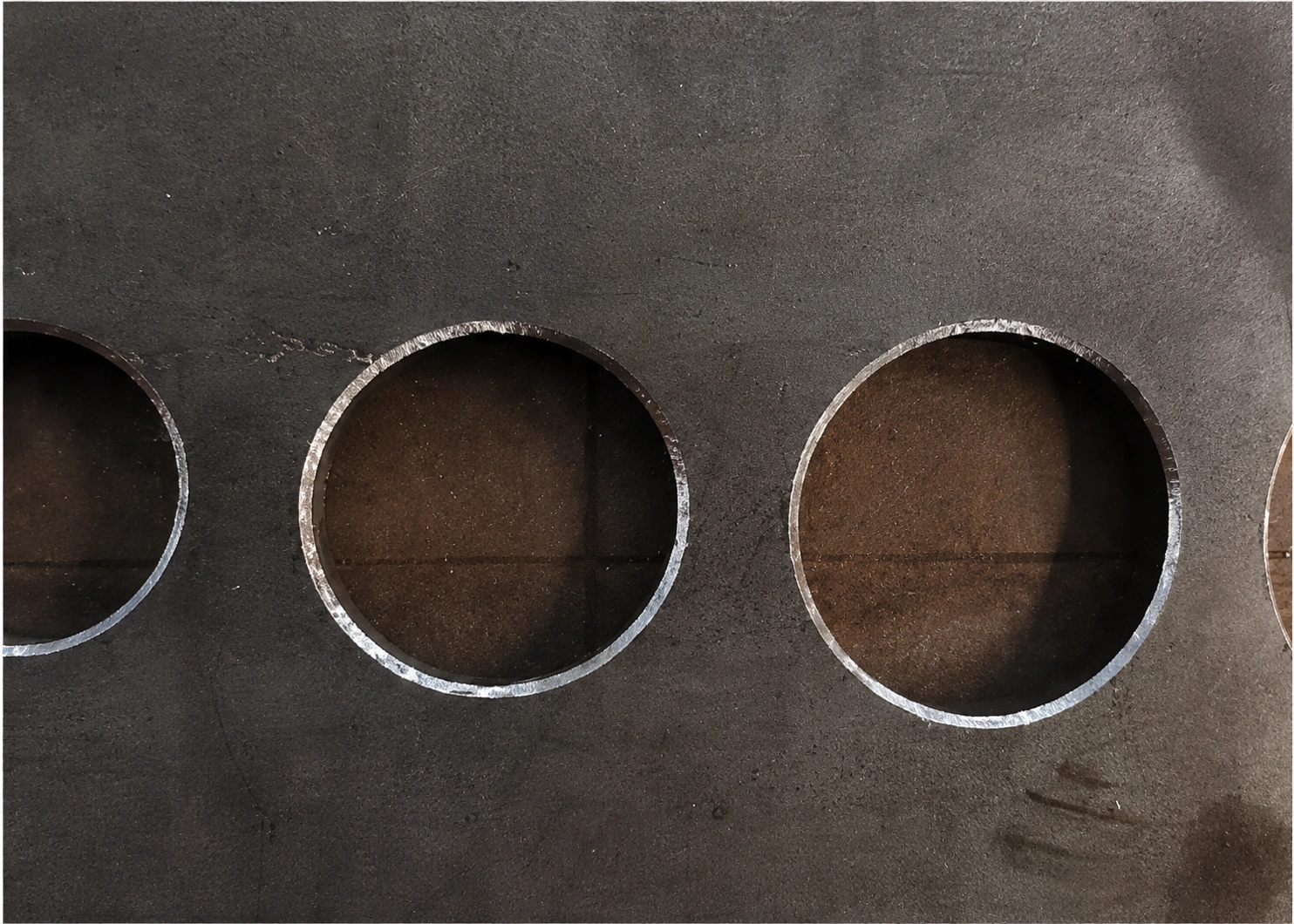
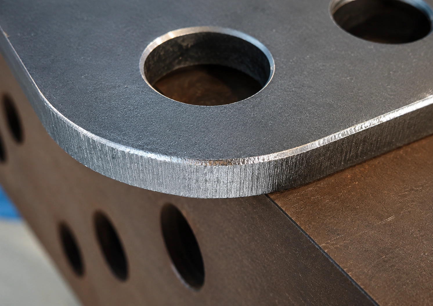
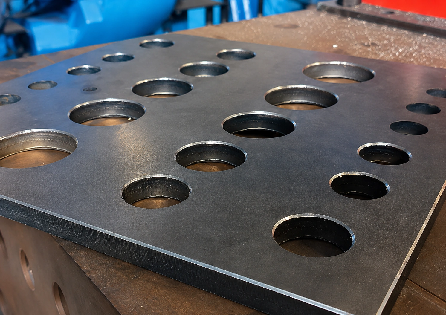
Organized into four capability groups: recognition and input, path generation, processing, and changeover/operation.
Recognition and input
Path generation
Processing
Changeover and operation
Fixed-program chamfering assumes repeating the same contour. When hole diameter, radius, perimeter length, or corner conditions change per workpiece, paths must be rebuilt. Recognition and geometry-matched path generation are designed to reduce that burden.
Zones of continuous arcs. When hole diameter or radius changes, fixed trajectories often need point rework. As-built geometry is captured so arc paths can be matched.
Straights and curves mix, and outer profiles change by part family. Hand-teaching a full perimeter adds programs at every changeover.
Corners require path and head-attitude transitions. Fixed paths are prone to interference or incomplete finish in these zones.
Profiles outside standard contours. Model input and as-built recognition are combined so paths follow that workpiece’s edges.
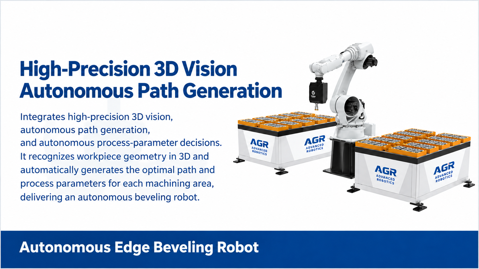
Speed, accuracy, plate thickness, and cycle time depend on workpiece and process conditions.
Factory production application of teachless bevel cutting as a weld-preparation process.
Customer-facing application of high-mix robotic welding automation for H-beam fabrication.
A fixed robotic bevel cutting system is a stationary layout with a defined work envelope. Features such as mirroring visualization, batch processing, one-touch start, and continuous multi-workpiece processing belong to fixed configurations. A floor-traveling robotic bevel cutting system moves across a wider area with 7-axis coordinated motion and flexible task planning. Neither configuration is a welding-robot camera remounted for cutting.
Typical targets include thick-plate structural parts for construction machinery, mining equipment, bridge steelwork, shipbuilding, and wind energy. High-mix, low-volume one-off production is also in scope. Distortion-prone workpieces and compound bevels are evaluated by configuration. Final specification depends on confirming actual workpiece conditions. Current scope is automated bevel cutting by gas cutting only.
Bevel cutting prepares joint geometry for welding. Chamfering finishes edges such as hole perimeters and outer contours. Both are pre-weld processes, but they are different. Deburring is a secondary edge finish available on compatible chamfering robot configurations — it is not synonymous with bevel cutting or chamfering.
It supports diverse workpiece shapes including straight lines, arcs, and curves. Processing examples include circular holes, radius corners, outer edges, right-angle corners, and irregular workpieces. 2D/3D inputs (DXF, DWG, STEP, IGS) are supported. Shapes that are hard to program with fixed paths benefit most from recognition and path generation matched to the workpiece geometry.
On compatible teachless chamfering robot configurations, free-edge chamfering can include automated deburring as a secondary step. The primary purpose is chamfering. Deburring is not a dedicated product and is a different process from bevel cutting.
No. Cutting and bevel preparation recognize contours and bevel geometry; welding vision recognizes joints and weld candidates. Each is designed for its workpiece conditions. This is not a shared vision system with only the end-of-arm tool swapped.
Current scope is teachless bevel cutting by gas cutting only. Laser cutting, plasma cutting, and other cutting methods are not in scope.
AGR provides remote and on-site technical support for delivered systems, including installation and commissioning, operator training, system setup, troubleshooting, maintenance support, and production ramp-up. Service scope is coordinated according to the system configuration, delivery region, project requirements, and agreed service arrangement.
Engineering support and technical coordination for delivered AGR systems.
Toronto, Ontario, Canada — regional communication and service coordination for North America.
Incuba Navitas, Inge Lehmanns Gade 10, 6th Floor, DK-8000, Aarhus C, Denmark — regional communication and service coordination for Europe.
+45 5376 5172
[email protected]
Regional parts availability: Common consumables and selected service parts can be stocked regionally based on installed systems and service requirements to reduce parts lead time and support faster maintenance response.
Material, plate thickness, bevel geometry, and drawings help the Global sales team progress a technical assessment.
Discuss Bevel Cutting for Your Application Request a Workpiece Evaluation