
Press load/unload and inter-process transfer
Material Handling & Process Automation Line
AGR designs case-specific automation lines by combining transfer, load/unload, inter-process transfer, assembly, machining, welding, and other required steps to match the real production process. The project example below is an automated transfer line for a press process.
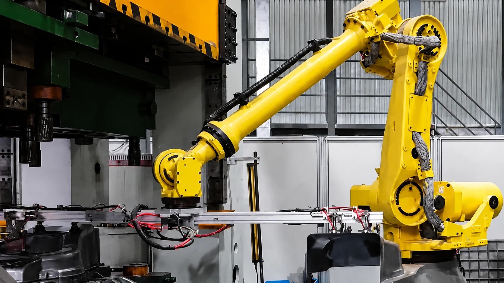
A line that connects process steps.
Where a Robotic Welding Line centers on connecting welding steps, a Material Handling & Process Automation Line builds a line that can include non-welding steps as well. Inspection and electrical-control scope vary by project. Layouts are designed case by case to match the workpiece, process, and volume.
Elements that make the line work.
Robots or handling mechanisms, workpiece supply, positioning, transfer, stations, safety, and centralized control are combined to match project conditions.
Robot / handling mechanism
Mechanisms that hold, transfer, and load workpieces.
Workpiece supply & positioning
Supply method and positioning accuracy matched to the process.
Transfer & stations
Inter-process transfer and the role of each station.
Safety
Guarding, interlocks, and the boundary between people and equipment.
Centralized control
Manages the line operating sequence, fault handling, and recovery actions.
Project-specific layout
Designed to match plant layout and material flow.
From supply to discharge.
The following is a baseline flow when assessing a line. Not every project includes vision, inspection, or higher-level system integration.
- 01
Workpiece supply
Load target workpieces onto the line.
- 02
Transfer
Transfer that connects stations.
- 03
Positioning
Secure the attitude and position needed for the next step.
- 04
Machining, assembly & welding
Perform machining, assembly, welding, or other steps as the project requires.
- 05
Inter-process transfer
Transfer between process steps.
- 06
Discharge
Discharge finished parts or hand them to the next process.
Lawn-mower housing press-process automated transfer line
A real project in which five transfer robots handle load/unload and inter-process transfer in the press process for lawn-mower housings.
Configuration example
- Five transfer robots
- Press-process load/unload and inter-process transfer
- Positioning and preparation at supply (vacuum suction, telescopic suction, positioning)
- Robot end-of-arm tooling (suction and gripping)
- Inline inspection before downstream processes
- Safety guarding and interlocking
- Full electrical control package including PLC and HMI, plus startup
- Operation visualization and alarms
Process steps on this project
Workpiece supply & positioning
Orient supply workpieces and raise grip reliability.
Robot grip
Hold the housing with the robot end-of-arm tooling.
Press load
Load the workpiece into the press process.
Press unload
Unload the workpiece after processing.
Inter-process transfer
Transfer to the next station.
Inline inspection
Identify nonconforming parts before downstream processes.
Downstream process
Hand inspected workpieces to the next process.
Safety, electrical/PLC, and HMI/monitoring wrap the line as a whole. Whether inline inspection is included—and its scope—is designed to match the project’s process requirements.
Replace manual transfer
Robots handle press load/unload and transfer, reducing manual-transfer burden and lowering the need for operators to enter the press work zone.
Stable handling
Repeatability, supply-side positioning, and reliable gripping reduce housing collisions and marks and protect appearance quality.
Inspection before downstream
Inline inspection identifies nonconforming parts and lowers rework and scrap risk downstream.
Response to specification change
Layouts are designed so specification changes are mainly addressed by end-of-arm tooling swaps and positioning-parameter adjustments. Fit is decided after confirming workpiece and equipment conditions.
Operation visualization
Line status, alarms, and fault-state visibility make root-cause identification easier.
Safety and electrical control
Safety guarding and interlocks, plus PLC, HMI, and control panels, are supplied as one package to reduce multi-vendor coordination.
Organize the line before handing work to downstream processes.
Inline inspection
A station layout that can include vision and related software plus safety light curtains identifies nonconforming parts before downstream processes. Inspection targets and judgment criteria are set to match the workpiece and quality requirements.
Safety
Safety guarding and travel/limit-switch interlocking reduce the need for people to enter hazardous zones around the press. Safety equipment is designed to match the target process and equipment layout.
Full electrical control package
PLC, touch panel, control panel, indicator lights, wiring, and startup are delivered as one package. Lead time is set case by case after confirming equipment specifications and process scope.
Modular design
Raises equipment reuse and makes product-change response easier. Not every new part number can be handled by parameter changes alone.
What can be built into the line.
- Transfer
- Load / unload
- Press-process automation
- Inter-process transfer
- Multi-process connection
- Workpiece handling
- Project-specific layout
Live equipment motion for a Material Handling & Process Automation Line
Confirm live equipment layout and motion. The video loads and plays after click (no autoplay).
Video loads and plays after you select it; autoplay is disabled.
Discuss a project
Process diagrams, target workpieces, material flow, and plant layout help the first organization move faster.
Discuss a project